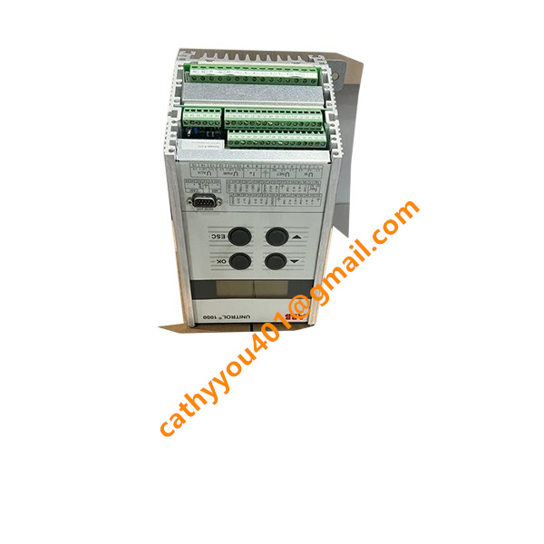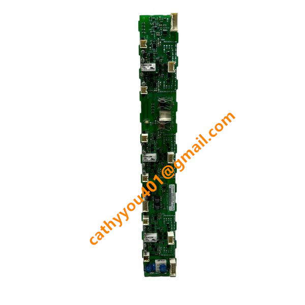













Description
-
BrandABB
-
Model3HAC17484-1/02
-
Product NameRobot Servo Motor with Pinion Gear
-
Place of OriginSweden
-
Customs HS Code85015200
-
Power Supply230 VAC
-
Dimensions235 mm × 132 mm × 118 mm
-
Weight6.2 kg
-
Operating Temperature‑10℃ to +55℃
-
Storage Temperature‑40℃ to +85℃
-
Warranty12 month
-
Product Statusbrand new
ABB 3HAC17484-1/02 (Robot Servo Motor for IRB7600)
This is an ABB robot axis servo motor without general-purpose digital or analog process I/O. Its interfaces consist of power winding, brake, and encoder feedback signals.
Power Signals (Motor Power Connector)
U: Motor phase U
V: Motor phase V
W: Motor phase W
PE: Protective earth
BR+: Brake positive supply
BR-: Brake negative supply
Encoder Feedback Signals (Signal Connector)
Data+: Serial encoder positive
Data-: Serial encoder negative
+5V: Encoder power supply
DGND: Digital ground for encoder
VB+: Backup battery positive
VB-: Backup battery negative
Shield: Cable shield, connected to motor housing
Internal Motor Sensor Signals
PT100 / PTC: Motor winding temperature sensor input (feedback to drive unit)
Thermal Warning: Motor over-temperature status signal output

Installation and Commissioning Procedure for ABB 3HAC17484-1 Servo Motor (IRB7600 Robot Axis Motor)
Safety Preconditions
Cut off the main power supply of the IRC5 controller and implement lock-out-tag-out prior to all mechanical and electrical operations.
Mechanically secure robot axes to avoid unintended movement throughout motor replacement work.
Wear appropriate personal protective equipment and comply with official ABB robot safety requirements.
Mechanical Installation Steps
Dismantle protective covers of the robot arm to gain access to the motor mounting location.
Relieve pre-tension on the matched gear unit, and precisely align the motor shaft pinion with the gearbox input gear.
Mount the new 3HAC17484-1 servo motor to the mounting flange. Tighten mounting bolts to the required torque using a cross-tightening sequence.
Inspect gear meshing condition between motor pinion and gearbox gear; manual shaft rotation shall show no jamming or abnormal friction.
Fit sealing gaskets properly to guarantee intact IP protection, then reinstall mechanical protective covers.
Electrical Connection Steps
Wire the motor power connector, including U/V/W motor phases, PE protective earth, as well as BR+ and BR- brake cables.
Terminate the encoder signal connector: Data+ / Data- serial encoder signals, +5V encoder power supply, DGND digital ground, VB+ / VB- backup battery signals, and connect cable shield to motor housing.
Lay the motor cable harness following the original routing layout; fasten cable clamps to prevent cable tension, torsion and abrasion against sharp edges.
Re-verify all connector latches are fully locked; make certain there are no loose pins or damaged cable insulation.
Commissioning & Calibration Procedure
Re-energize the controller and boot up the IRC5 robot system.
Access the calibration menu via FlexPendant, and shift the corresponding robot axis to its mechanical zero position.
Carry out revolution counter reset for the replaced axis, and complete axis fine calibration in strict accordance with ABB standard procedures.
Conduct brake function test to ensure the electromagnetic brake engages and releases smoothly without abnormal noise.
Operate the target axis in low-speed jog mode, monitor encoder feedback values, motor current and operating temperature.
Run continuous no-load jog test; check for abnormal vibration, noise and overtemperature alarms.
Implement full-stroke movement test for the axis to validate positioning accuracy and dynamic performance conform to technical specifications.
Post-Installation Inspection
Monitor motor temperature rise after 30 minutes of continuous running.
Check system logs to ensure no fault codes triggered by encoder, brake or motor phase failures.
Create a complete system backup once installation and commissioning are finished successfully.

GDB021BE
Unitrol 1020
698B275U01
SM810K01
BC810K02
PP886
PBA800
RED615



.jpg)